Types of Compressors
|
Reciprocating Compressor
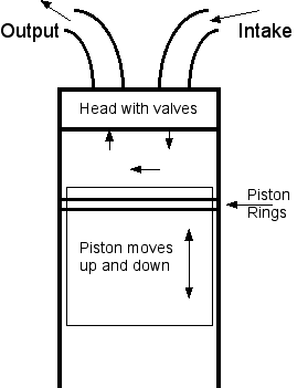
Reciprocating air compressors are the type of compressor found in most small shops, they are positive displacement machines. This means that they increase the pressure of the air by reducing its volume, this is accomplished by a piston moving up a cylinder compressing the air above it. Single-stage and two-stage reciprocating compressors are commercially available. Single-stage compressors are generally used for pressures in the range of 70 psi to 150 psi. Two-stage compressors are generally used for higher pressures. |
|
Rotary Screw Compressors
Rotary air compressors are also positive displacement compressors. The most common rotary air compressor is the single stage helical or spiral lobe oil flooded screw air compressor, consisting of two rotors within a casing where the rotors compress the air internally. There are no valves. These units are basically oil cooled with the oil sealing the internal clearances. Since the cooling takes place right inside the compressor, the working parts never experience extreme operating temperatures making them continious duty compressors. |
|
Centrifugal Compressors
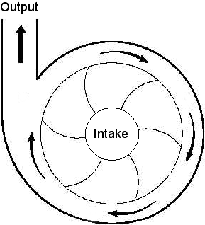
The centrifugal air compressor is a dynamic compressor which depends on a rotating impeller to compress the air. In order to do this efficiently, centrifugal compressors must rotate at higher speeds than the other types of compressors. These types of compressors are designed for higher capacity because flow through the compressor is continuous and oil free by design. |
Basic Compressor Components

| Compressors come in many different styles, the drawing above is of a typical horizontal tank model, smaller models may have wheels at one end and a handle at the other so the compressor can be moved around. Other models may have a tank that stands up on its end with the motor and pump mounted on top of it. A third style will have single or dual tanks in a wheelbarrow configuration for easier portability. Whatever the style it will be made up of at least these basic components.
1. Air intake, pumps sucks air into cylinder through this filter. 2. Compressor pump, may have one or more cylinders with a piston and crankshaft similar to a gas engine, or a rotary vane. Through a system of valves in the head air is drawn in and then forced out under pressure into the holding tank. 3.Outlet, compressed air enters the tank through this pipe, it may be coiled or finned to help cool the air. There will also be a check valve in this line to allow the air from the pump to flow to the tank but not back out of the tank. 4. Drive belt, depending on size of pump there may be two or more belts, some models have a direct drive coupling between the motor and pump. 5. Motor, this drives the pump, may run on 110 volt or 220 volt current depending on size of unit. 6. Control switch, automatically switches motor off and on at predetermined settings. 7. Relief valve, opens to release air in tank if pressure exceeds a safe limit. 8. Pressure gauge, measures pressure of air in the tank. 9. Manifold, a fitting with several outlets to connect control valve, pressure relief valve, gauge, etc. 10. Regulator, controls the amount of pressure leaving the tank. 11. Supply line, feeds air to tools, will likely have water traps installed as well. 12. Air tank, special tank built to withstand high volume of air pressure must be certified as an air tank. 13. Water drain, valve to drain water that collects in tank, automatic drains are available, otherwise these should be manually opened to drain water frequently. |


