"Helping Woodworkers Online For Over 20 Years"
Cutting Dovetails - Secret Mitre - Machine Cut - Dovetail Grooving - Dovetail Keying - Marking Jig - Puzzles
Cutting Dovetails - Secret Mitre - Machine Cut - Dovetail Grooving - Dovetail Keying - Marking Jig - Puzzles
|
Nothing definite is known as to the origin of dovetailing, but a quaint and pleasing little story which is well worth repeating runs as follows: A farmer had called in the local "joyner" to do sundry repairs at the homestead. One day, whilst enjoying a humble meal, he sat watching some doves as they hopped about the yard. Struck by the movement of their wedge-shaped tails, it occurred to him to joint his timber by the interlocking method; hence we have dovetails.
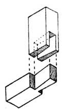
Fig. 267.—A Single Through Dovetail. |
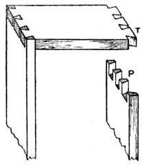
Fig. 268.—Through Dovetails on Carcase Work (P, Pins; T, Tails). |
Through Dovetailing.—One of the simplest forms of the dovetail joint is shown in Fig. 267, where two pieces of timber are joined by the method known as "through" dovetailing. This method is used in everyday practice for joining the corners of frames, bracket trusses, and a hundred and one other articles.
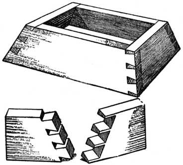
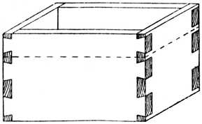
Figs. 268 and 269 show the method of through dovetailing as applied to the making of boxes, plinths, and general carcase work; it is used in positions where no objection can be taken to the end grain showing on each side of the finished work. In the case of plinths and furniture cornices the foundation frame is made of yellow pine or other cheap wood, and the more expensive and rare timbers are glued and mitred around in various thicknesses and shapes, thus saving the more costly material and strengthening the construction by the method known as laminating. In many cases all that is necessary is to veneer the face sides, thus covering and hiding any unsightliness.
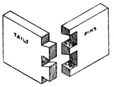
Fig. 269.—Dovetails for Boxes, etc. |
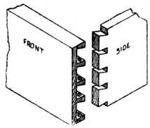
Fig. 270.—Lap-dovetailing for Drawers. |
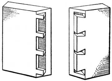
Lap-dovetailing.—Fig. 270 is an example of lap-dovetailing, such as is used where a drawer side joins with the drawer front. It is not permissible to allow the end grain of the timber to show at the front of a drawer, and this is why resort is had to the lap-dovetail. As the most general use of the dovetail is for this and similar purposes, we shall therefore deal fully with the methods of marking out and the making of this class of joint.
Angles.—A most important point in the construction of a dovetail is to avoid having the angles of the pins and tails too acute. An inclination of one in eight is considered correct; no hard and fast rule need be obeyed, but the variation should on no account be less than one in six.
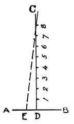
Fig. 271.—How to obtain Correct Angles for Dovetail Template. |
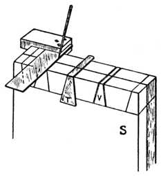
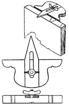
Fig. 272.—Squaring and use of Template. |
Fig. 271 shows a simple method to obtain the correct angle. Take a piece of timber and plane up the face edge (A, B) true and straight; mark out a line (C, D) at right angles to the face edge and space off 8 ins. as shown; now measure a distance of 1 in. (D, E), and join E to point eight. This will give the correct angle for the dovetails, and it may then be transferred to the joiners' bevel. Many workers who are constantly on dovetail work make a zinc template to the exact angle and keep it specially for the purpose (Fig. 272).
Squaring.—Another important point to remember is that the drawer sides must be true and squared to an exact length and planed up to thickness; otherwise the finished drawer will be in winding and out of truth.
To true and square the ends of drawer sides, drawer backs and drawer front, a most useful little machine is the mitre trimmer; failing this, excellent results can be obtained by using the shooting board.
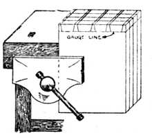
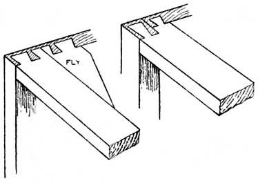
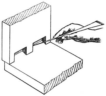
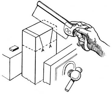
Gauging.—After squaring up the timber accurate gauging of the ends is another important point. The gauge used should be a cutting gauge, so that the line is incised about 1⁄32 in. in depth, thus effectually cutting the cross fibres of the timber.
Fig. 273 shows the method of using the cutting gauge. The stock of the gauge must be held well up to the end of the timber. The gauge is a most difficult tool for the novice to use, and his trouble is generally caused by holding it too flat. Tilt the gauge a little so that the thumbscrew shown in the illustration goes nearer to the floor; the blade will then not bite so keenly, and better results will be obtained. The dotted lines indicate the positions which the dovetails will occupy when marked out.
The gauge is set a trifle less than the thickness of the drawer sides to allow for the thickness of the steel cutter, and a gauge line is marked on the inside of the front and all round the drawer back. The gauge is now readjusted so as to leave a 1⁄4-in. lap on the front, and a line marked on the ends of the front and all round the ends of the sides which will engage the drawer front. A glance at Figs. 270 and 273 will make this clear.
The dovetail pins on drawer part and back are spaced out and marked on the end with the aid of the joiners' bevel, the lines being then squared down to the gauge line by the method shown at Fig. 272—that is, by using the try-square and marking awl.
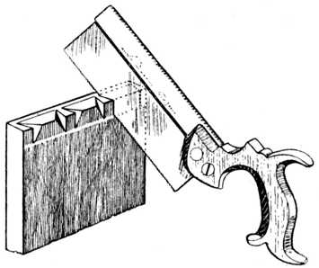
The drawer front is now put into the bench vice, and the pins are cut as indicated in Fig. 274. The drawer back is treated in a similar manner, but of course in this case it is not "lap" but "through" dovetailing, and the saw kerf goes through the timber and down to the gauge line.
We now come to the point where it is necessary to remove the superfluous material. Fig. 274 shows a method commonly adopted and known as sawing out the waste; the saw is held at an angle and part of the inside portion of the dovetail is cut away as shown. This is a good plan for the amateur, because it shows him at the commencement of his chopping out which will be the pin and which the tail.
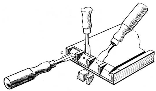
Fig. 276 (A) shows another method that answers well for soft woods such as pine, American whitewood and satin walnut. The drawer front is laid flat on the bench after it has been sawn, and with a mallet and sharp chisel the corner of the dovetail is knocked off as shown. This takes the bulk of the material away and the dovetail is then pared out square in the usual way. The illustration (Fig. 276) also shows how the chisel is held for vertical paring (B) and for horizontal paring (C).
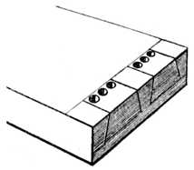
Fig. 277.—Roughing-out by Boring. |
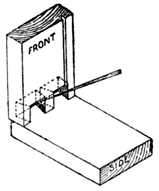
Fig. 278.—Marking Pins on Drawer Side. |
A third method is shown at Fig. 277. With hard, curly timbers, such as tobacco mahogany and satinwood, it is a laborious process to carefully chop away the timber in small pieces, and to overcome this difficulty we occasionally see the workman take a twist-bit and bore a series of holes as shown. A great portion of the timber may then be split away by inserting the chisel end-way into the grain, after which it is pared to a finish.
As dovetailing is chiefly used for drawer making, it will be of interest to give several illustrations of variations of the joint and its uses.
Fig. 278 indicates the method of marking the position of the holes in the drawer side. When the paring out of the dovetails is completed the drawer front is turned over on to the side as shown, and the position of the recesses which will engage the pin portions are marked with the marking awl as illustrated.
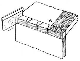
Fig. 279.—Marking by means of Saw Blade. |
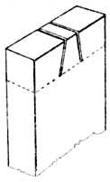
Fig. 280.—Gauge Lines, Scores and Saw Cuts. |
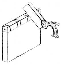
Fig. 281.—Sawing the Drawer Side. |
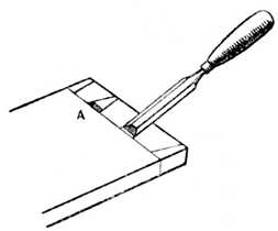
Fig. 282.——Position of Chisel for Cutting Channel. |
The completed drawer back is marked on the sides in an exactly similar manner.
Another method of marking through dovetails is shown at Fig 279. The side is held in position on the end, and the dovetail saw is inserted and drawn out of the saw kerf, thus leaving the exact mark on the drawer-back.
Other workers prefer a pounce-bag instead of a saw. A pounce-bag consists of a piece of fairly open woven muslin filled with a mixture of French chalk and finely-powdered whiting; the muslin is tied up with a piece of thin twine like the mouth of a flour sack. All that is necessary is to place the timber in position and bang the bag on the top of the saw-cuts, when sufficient powder will pass through the bag and down the saw kerf to mark the exact positions of the lines.
Sawing the Dovetails.—After marking out the pins on the drawer sides, we proceed with the next operation, that is, sawing the dovetails ready for chopping out the waste material. The drawer side is taken and firmly secured in the bench screw and sawn as at Fig. 281; it is most important that the saw kerf is kept inside the line which has been scratched by the marking awl. See Fig. 280, where the dotted line represents the gauge line and the outside lines indicate the scores of the marking awl. Failure to observe this condition will result in faulty dovetailing, and it will also prove the necessity for using a finely-toothed and thin-bladed dovetail saw.
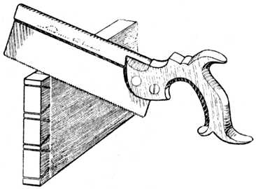
To cut out the waste wood (or core), the usual procedure is to saw away the half-dovetails as at Fig. 275. With care, this can be accomplished with the dovetail saw, thus avoiding unnecessary labour and the use of the paring chisel.
After sawing, the drawer side is placed flat upon the bench, one end in contact with the bench to prevent the drawer side from slipping away; a chisel (preferably bevelled edged) of suitable width is now taken and a small channel is cut as at A, Fig. 282. The method of cutting this channel is shown in the same illustration. The chisel-cut is started about 1⁄8 in. from the gauge line; the cut is made right up to the gauge line, which (when gauging) was made 1⁄32 in. deep so as to cut the cross fibres of the timber. A small piece of waste wood will therefore come away as at A.
The object of cutting this small channel is so that, when the chisel is held vertically on the gauge line and struck with the mallet, the chisel will have no tendency to force its way backward and overshoot the gauge line. The waste or core is now removed by holding the chisel approximately vertical and applying sufficient power to drive it half-way through the timber. The drawer side is now turned over, the operation repeated, and the core pushed out. Care must be exercised whilst cutting away the core to ensure the chisel being held nearly perpendicular; if too much lead (or bevel) be given, a faulty and undercut dovetail will be the result. Undercut dovetails prevent a proper grip of the glue; they give a weak joint, and often cause the face of the drawer side to be splintered whilst driving up the joint. If it be necessary to ease one or two shavings from off the drawer side whilst fitting the completed drawer in the carcase, the joint will show a greater gap as each succeeding shaving is removed.
In common work, especially in soft timbers, many workers allow the pins of a drawer back to run through the sides about 1⁄16 in. and hammer down the pins of the dovetail. This is called "bishoping the dovetails," and is unnecessary if the work be properly made and fitted.
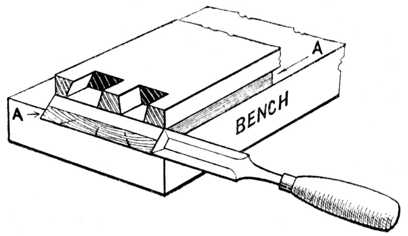
An alternative method of dovetailing is that of cutting the dovetails first, as shown at Fig. 283. Four or six drawer sides are placed in the vice and the dovetails are sawn at one operation. A little lead (or bevel) from front to back is given whilst sawing, and if this method be used care must be taken to see that the parts of the drawer sides which will be on the inside of the completed drawer are towards the worker, or the lead will be given to the dovetails in the wrong direction.
After sawing the dovetails in this manner the sides are placed in their respective positions on the drawer fronts or backs, and marked with a pounce-bag or by using the saw-blade method. The pins are then cut in the usual way, care being taken that the saw kerf be on the outside of the marks, otherwise the pins will finish too slack to engage with the tails.
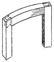
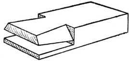
Frame Dovetails.—Fig. 284 is a sketch of a constructional frame such as is used for building up a cornice or plinth. At the joint marked A an edge barefaced dovetail is shown. From the separated sketches of the joint (B) it will be seen that the dovetail can be put together either from the top or the bottom of the framing as all its edges are parallel; glue is relied upon to hold it in position. The centre stretcher rail at Fig. 284 is similar, except that in this case it is a complete dovetail in place of a barefaced one.
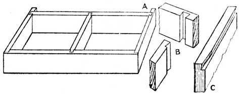 Fig. 284.—Constructional Frame (as for Plinth or Cornice) showing application of the Dovetail Joint.
Some workers, when making either of the above joints, prefer to give a slight bevel to the dovetail, so that it drives tightly into the housing when put together.
A variation of this type of dovetail is frequently used to joint internal uprights to the horizontal shelves of writing desks, cabinets, and bookcases, etc. The dovetailed portion is parallel for about three-fourths of its width; the remaining part is tapered towards the front edge and notched away at the face so as to conceal the method of construction. An illustration of the top portion of a division 14 ins. wide is shown at Fig. 284, C. The other portion is of course dovetailed to fit it.
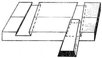
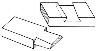
Blind Lap-Dovetailing.—At Fig. 285 is shown a type of blind lap-dovetailing. This makes a good, sound joint, but it has the disadvantage of showing a small portion of the timber of the front rail end-way of the grain. Joints of this kind are used for cornices, boxes, etc., and also for painted furniture.
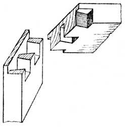
Fig. 285.—Blind Lap-Dovetailing. |
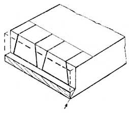
Fig. 286.—Housed and Mitred Dovetail. |
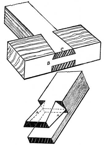
Housed and Mitred Dovetail.—Fig. 286 is another form of dovetail—commonly called a housed and mitred or rebated and mitred dovetail. In this instance we see that a small portion is mitred at top and bottom edges, and when used in plinth or cornice work, or for making tea-caddies, etc., the edges are (when completing the work) covered either with the moulding, which is planted on the cornice or plinth, or with the top and bottom of the box or tea-caddy.
The method of making a housed and mitred dovetail joint is seen in Fig. 286. The ends to be joined are planed up true and square and then rebated as shown. The dotted lines indicate the portion which has been worked away. The dovetails are now sawn and pared out in the usual way and the part denoted by the arrow is afterwards cut away with a chisel and finally finished to a smooth surface with a rebate plane; the method of working is shown at Fig. 287, where the dovetail pins are seen with the waste portions cut away.
Fig. 287 also shows the method of cutting away the mitred part. A temporary piece of wood is planed to a true mitre and placed underneath the dovetailed piece to form a template. Both pieces of the timber are now secured to the bench with a handscrew or cramp; the template A will form a guide for the chisel and rebate plane and allow a sharp edge or arris to be worked on the mitre.
A Secret Mitred Dovetail joint is illustrated at Fig. 288; it is used in all the better class of cabinet and box work. Fig. 288 shows the pieces separated; note the mitre at the top and bottom edge.
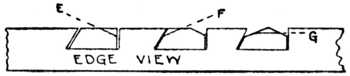
Dovetail Keying.—Fig. 289 is a method used to prevent wide boards such as signboards, wide and shaped pediments, etc., from casting or warping. It is called dovetail keying. Beyond calling attention to the fact that the angles at the edges of the keys, where they are bevelled, should be at or about 75 degrees, nothing further need be said, as the drawing is self-explanatory. Angle dovetail keying is shown at Figs. 290 and 291.
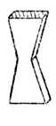
Fig. 290.—Dovetail Key. |
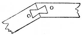
Fig. 291.—Dovetail Keying on the Angle. |
Other Varieties.—At Fig. 292 we have an everyday method of jointing circular-fronted cabinet door frames. Great care must be taken in setting out and making, or a twisted frame will result.
Then at Fig. 293 are shown two familiar examples of dovetailing the bearer to the carcase end of a dressing table or washstand.
Fig. 294.—Lap-dovetailing the top of a wardrobe to the carcase end. Other examples, such as the top of a bookcase to the sides, will suggest themselves.
Fig. 295.—Side view of a jewel drawer with a moulded drawer front as used on dressing tables, etc. This shows the necessity of bevelled dovetailing in order that the drawer front may be kept as thin and light as possible.
Fig. 296.—Bevelled dovetailing when pins are at right angles to the end cut.
Fig. 297.—Bevelled dovetailing when the centre line of the pins is parallel to the edges of the work, used for making "hoppers," food troughs, knife boxes, etc. One corner of the box shows the joint separated.
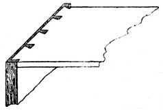
Fig. 294.—Lap-Dovetailing. |
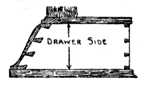
Fig. 295.—Jewel Drawer Side. |
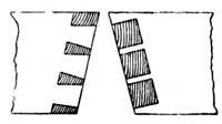
Fig. 296.—Bevelled Dovetailing. |
Fig. 298.—An example of oblique dovetailing, as used on "hoppers" when one piece is vertical and the other piece is inclined.
Fig. 299.—Method of dovetailing small boxes. The box is dovetailed in one width and the top and bottom glued on; the sides and ends are then cut along the dotted line, thus forming the lid. It will be noticed that a specially wide dovetail pin must be left so as to form part of the lid and part of the lower portion.
Setting out the Joint.—For constructing a dovetail joint at the corner of a frame, as Fig. 300, it is necessary at the outset to trim up the ends of the timber square and true. This may be accomplished by neatly sawing to the line and paring the end of the wood with a sharp chisel, or by bringing the wood to a finish with a finely-set plane, such as an iron-faced smoothing plane. The ends of the wood must be perfectly square when tested from either the face side or from the marked edge.
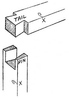
Fig. 300.—Corner Dovetail. |
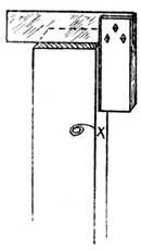
Fig. 301.—Squaring. |
Take a cutting gauge and set it to equal the thickness of the timber, and, holding it as already shown at Fig. 273, strike the gauge lines on the wood as illustrated at Fig. 302, G. Proceed to mark out the dovetail pins, as at Fig. 303; in this illustration G again shows the gauge line. The inclination of the lines across the end of the wood should not be too great, or the joint will be a weak one, and the edges of the dovetails will be liable to crumble away when the work is knocked together.
Dovetailing Template.—Many workers who are constantly engaged upon dovetail joints make a small wooden template, as shown at Fig. 304. This template is generally of hardwood, such as beech or walnut. The method of obtaining the correct angles of such a template has already been given on p. 134. Notice that the lines bb (Fig. 303) of the dovetail pins do not bevel; they are parallel to the sides of the wood and at right angles to the end of the wood as shown.
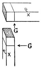
Fig. 302.—Gauging. |
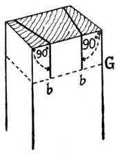
Fig. 303.—Marking the Pins. |
Chisel Work.—After marking out, as shown at Fig. 303, place the wood on the bench and proceed to chop away the centre portion in the following manner. Hold the chisel on the bevel and cut out a small piece to form a channel at the gauge line. Now hold the chisel in a vertical position, and with a mallet strike it so as to make a cut about 1⁄8 in. deep. Then hold the chisel on the bevel again and cut away more waste wood; proceed alternately, first forcing the chisel down vertically, and then paring the wood away with the chisel held obliquely, until you have cut half-way through the thickness of the wood.
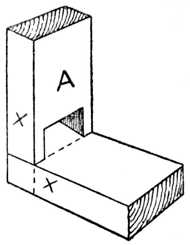
Fig. 305.—Testing. |
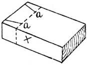
Fig. 306.—The Marked Piece. |
Turn the wood over and repeat the various operations until the core, or waste piece, is removed. Pare away any little irregularities which may be left in the corners with an 1⁄8-in. chisel, thus leaving all smooth and neat. Lay the piece of wood which is to have the dovetail marked on it flat upon the bench, and take the piece with the dovetail pins cut upon it and place in the position shown at Fig. 305.
Saw Work.—Take a marking awl, or a knitting needle which has had its end sharpened, and mark the lines of the dovetail in a similar manner to that shown at Fig. 307. Remove the piece A, Fig. 305, and the lower piece shown at Fig. 305 will clearly show the marks aa as they appear in Fig. 306. Place the piece (Fig. 306) in the vice, and saw outside the lines AA, as shown in Fig. 308.
After sawing down the lines AA, Fig. 308, place the wood in the vice and, guiding the saw blade with the index finger of the left hand, cut away the small piece at the side (see Fig. 275). Repeat the operation as may be necessary, and the completed joint will be similar to that shown at Fig. 300. If the sawing is not neatly done it may be found necessary to pare the shoulder with a sharp chisel.
Drawers.—When dovetailing drawers or boxes it is necessary to square up the ends of all the stock and gauge them, as shown at Fig. 273. This illustration shows how to gauge the lines on a drawer side; the dovetailed joint in this case, however, does not run through the drawer front and leave the work unsightly, as the joint at Fig. 300 would do. The method used is shown at Fig. 309, and it is commonly known as lap-dovetailing. Most workers cut the dovetail pins on the drawer fronts and the drawer backs first, after which they mark the drawer sides with the marking awl. The dovetailing of the drawer back is shown at Fig. 310. This is the type known as "through dovetailing," the method being similar in regard to tool operations as the single joint shown at Fig. 300.
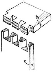
Fig. 310.—Through Dovetailing. |
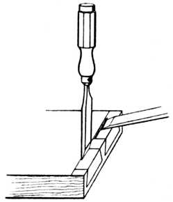
Fig. 311.—Chipping Waste of Lap Dovetail. |
When the pins on the drawer front have been sawn, the waste material is cut away, as at Fig. 311. First stab down with the vertical chisel, which must make the cut about 1⁄32 in. in front of the gauge line (see illustration). This commencing of the cut slightly in front of the gauge line is a very important feature. The chisel may be likened to a wedge, and if the chisel edge be placed exactly upon the gauge line and force be applied to the handle, it will force the timber away equally on each side of the gauge line, and the finished depth of the hole will therefore be too deep for the thickness of the drawer side; in other words, it will press itself over the gauge line on both sides.
By taking the first vertical cut on the waste side of the gauge line, and then removing a small piece with the chisel held obliquely, as at Fig. 311, the wood is removed and less resistance is offered to the chisel when the next vertical cut is made. This overshooting the gauge line is a common fault with the beginner, who is puzzled at the result because he is certain he had his chisel exactly on the gauge line when he commenced his vertical cut. It is especially noticeable in soft-grained woods.
To cut away the waste of a lap-dovetail (Fig. 311), the vertical and oblique cuts are repeated until the final trimming up is required, and now is the time to finish both the vertical and the horizontal cuts exactly on the gauge lines.
Some workers prefer to cut the drawer sides first, and if this method is preferred (and it has its advantages for cheap work) several drawer sides are cut at once by placing four or six behind one another in the vice and sawing them all at one operation.
The drawer front is placed in the vice, and the drawer side held upon it, whilst the saw blade is placed in the saw kerf and drawn smartly forward. This will give the required marks at the exact position desired. It must be remembered, however, to saw just inside these dovetail-pin lines, otherwise the finished joint will be too slack, owing to the removal of the sawdust, which is practically equal to the thickness of the saw blade.
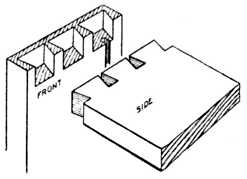
Machine-made Dovetails.—As a general rule machine-made drawer and box dovetails show both the pins and the tails of exactly the same size. The reason is obvious after an inspection of Fig. 314, which shows the position in which the pieces are held during the machining operations. In spite of a certain amount of prejudice they are satisfactory and thoroughly reliable and have their place in modern shop and office fittings.
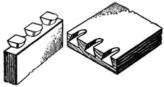 Fig. 312.—Machine-made Drawer Front and Side, Apart.
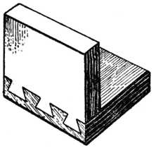
Fig. 313.—The Parts Together. |
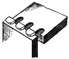
Fig. 314.—Position when Machined. |
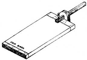
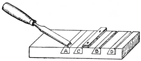
The dovetail housing joint should first be carefully marked out with a marking knife, so as to cut across the fibres of the wood. For obtaining the bevel on the edge of the wood a joiner's bevel may be used, and the angle should not be too acute. (See previous chapter.) Take a chisel and pare away a small channel as at A, Fig. 315, to form a small shoulder to guide the saw.
With a fine tenon or dovetail saw, cut the saw kerf as at Fig. 316. If any difficulty is experienced in cutting the kerf true and square, you may resort to the method shown at C, Fig. 315; a small temporary piece of timber has been screwed on the top of the work to form a guide for the saw.
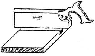
Fig. 316.—Cutting the Saw Kerf. |
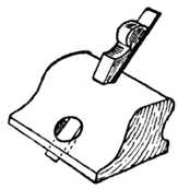
Fig. 317.—Old Woman's Tooth Plane. |
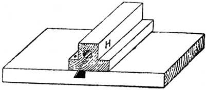
Fig. 315, B, shows the small channel formed by the chisel prior to the sawing operation. The sawing of the bevelled side is worked in a similar manner; but occasionally we find amateurs who adopt the method shown at Fig. 318. A block of wood (H) is first made by boring a 11⁄4-in. hole through its entire length, and afterwards making a saw cut at the desired bevel. The object of this block, which is kept specially for the purpose, is to form a guide for those who have not full control of the dovetail saw; the back of the saw clears the hole, and the required bevel is obtained. When a saw cut has been made at each side of the groove, the surplus timber is pared away in the following manner: Cut away portion E, Fig. 319; then cut away portion F, and lastly cut away the apex portion marked G. Continue by this method of paring until the approximate depth is reached. To ensure a correct depth throughout the entire groove, the router plane (or, as it is often called, "the old woman's tooth plane," Fig. 317) is used.
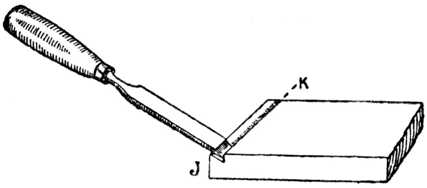
With regard to cutting the alternate piece, it is necessary to first plane the end of the shelf true and square. With a cutting gauge strike the line K, Fig. 320; the required bevel on the edge (J) is then set out, and with the chisel a small channel is again formed. With the tenon or dovetail saw cut down the line K to the required depth, and carefully pare away the wood with a sharp chisel to the correct shape.
The double dovetail puzzle (Fig. 379) consists of two pieces of wood (usually one dark and the other light) which, upon examination, appear to be dovetailed together from each face. This interlocking arrangement is obviously impossible, and the solution of the puzzle is only apparent on examining Fig. 380, where it will be seen that the joint fits together diagonally.
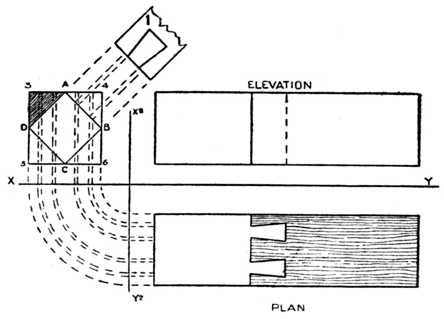
At Fig. 381 are given the diagrams for setting out. Draw the outline of the elevation, plan and end view. The end view in the first instance is indicated by 3, 4, 5 and 6, and it measures 17⁄8 ins. square. A 17⁄8-ins. square is simply used because 2-ins. wood generally finishes this size after it is planed up. Set out a square (A, B, C, D) which stands corner-ways in the larger square (3, 4, 5, 6). Project the lines D A and C B upwards as at 1, and on to this drawing (1), set out the dovetail according to your own idea of length, width and bevel. Project the four points of your dovetail downwards into the end view, and where these lines cut A, B, and D, C draw them downwards and rebate them into your original plan. This will give the true shape of the two dovetails and it is to this shape that you will cut your joint.
The joint is in due course glued up, and next day you will plane and waste off the four corners of your model. The end view shows one corner shaded D, 3, A; this and the other three corners are wasted away. The result is that the dovetails are thrown into a plane different from that in which they were made, showing as Fig. 379.
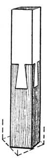
Fig. 379.— Double Dovetail Puzzle. |
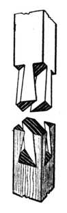
Fig. 380.— The Two Parts Separated. |
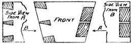
(Note that dovetail is cut on slant, the thickness at front being less than at back. See dotted line on plan below.)
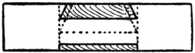 Fig. 384.—Plan, looking upwards.
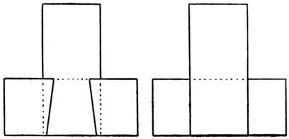 Fig. 385A.—Front Elevation. Fig. 385B.—Back Elevation.
The model calls for very accurate workmanship and the joints must not be undercut during the sawing and chiselling operations. The completed model measures 6 to 7 ins.
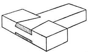
The Dovetail Puzzle joint illustrated at Fig. 382 has perhaps caused more argument and controversy amongst woodworkers than any wooden joint. It may be neatly made in maple, walnut, or mahogany, and afterwards glued up. The question everyone asks is: How was it put together?
Take two pieces of wood such as mahogany, walnut or birch, about 6 ins. long by 17⁄8 ins. wide and 11⁄4 ins. thick. Truly plane them up and then set out and make the tenon and dovetailed piece (Fig. 383). Next mark out and cut the cross bar to fit its corresponding piece. The joint will go together in a somewhat diagonal direction as it is pushed into position from the back; when closed it will appear as at Fig. 382. For guidance, a plan, part elevation and back elevation are added.
An improvement after you have gained experience in the making of this joint is to make a similar joint, leaving the face (B, Fig. 386) blind; it then does not show the bevelling of the dovetail at the end C. In other words, keep the line C, say, 1⁄4 in. back from the face of B. The joint should be glued up and it will then appear to the average worker that it is an impossible proposition.
Carefully note that the edges A, A are parallel to each other in spite of the fact that they slope in one direction.
A further variation of the puzzle is seen in Fig. 387. Here the joint is much simpler, and can easily be followed from the illustration.
|
|