"Helping Woodworkers Online For Over 20 Years"
Weather boards.—For outdoor buildings, such as garages, garden sheds, toolhouses, etc., "weatherboarding" is often preferred to ordinary matchboarding, chiefly because of the facility with which it throws off the rain. The boarding can be bought ready prepared. Three methods of jointing are shown in the sections at Fig. 343. The method indicated at A shows one of the most satisfactory types, its boards being planed and moulded as shown. The other two examples are more common. The boarding at B is rebated, whilst at C each board overhangs its lower neighbour. The boards for C and D are always cut tapered as indicated.
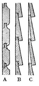
Fig. 343.— Weather Boards. |
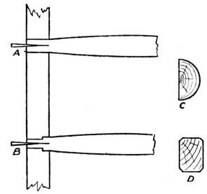
Fig. 344.—Ladder Rungs. |
The end grain is usually protected by nailing on a strip of timber, chamfered on both edges.
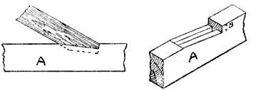
Ladders.—Fig. 344 illustrates the method of fastening the rung (or stave) of a ladder to the side. At A the common method is shown, the stave being simply driven into the hole and wedged. At B a much better but more expensive method of construction is given. The stave here is socketed and the pin turned to a smaller diameter. In both cases the rung, or stave, is painted before being driven into the side and wedged.
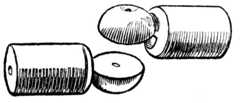
Fig. 345.—Cornice Pole Joint. |
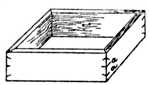
Fig. 346.—Veneer Keying. |
Ladder sides are made in two distinct ways. One method is known as "a plank side," the side being cut from a plank as shown at the section D; the other method is called "a pole side," and is constructed by cutting a straight larch pole in half and using half of the pole for each side of the ladder, as at section C.
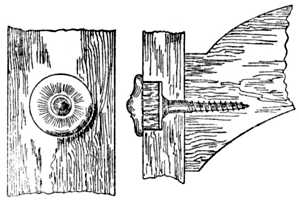
Hinged Cornice Poles.—Fig. 345 shows a hinged joint for cornice poles and should be of interest to those who are frequently removing from house to house. The joint will adapt itself to fit any bay window (even a square bay) and it is formed by turning and cutting the two pieces shown. To fix a cornice pole to a bay window one of these joints is required for each angle of the bay, the pole being cut into suitable lengths and fixed to the hinged joints by the use of the dowel screw and a little hot glue. It is perhaps needless to remark that the diameter of the joint should be of the same diameter as the cornice pole, to enable the rings to easily slide over the surface.
For fastening a turned ornament (or "finial") to the end of a cornice pole a double pointed screw (known in the trade as a "dowel screw") is used, one half of which is screwed into each part of the pieces to be joined.
Veneer Keying.—Fig. 346 illustrates the method of strengthening the corners of boxes which are made of 1⁄4-in. or 3⁄8-in. timber, by securing the corners with veneer keys. The box is mitred and glued in the usual manner, and after allowing sufficient time for the glue to set, saw kerfs are made as shown at a a. A piece of thin saw-cut veneer is afterwards glued into the saw kerfs, and when dry the face is levelled off flush. This method is often used previous to veneering the face side of the box with rare veneers, and it is also useful for repair work. Note that the saw cuts are made at an angle. Small picture frames are sometimes keyed instead of nailed.
Muntin and Skirting Joint.—In the case of panelled rooms it is usually necessary to scribe the muntins (or uprights) to the skirting. The method is shown in Fig. 347. The bead moulding of the skirting is only partly removed, as indicated, leaving a solid portion to which the muntin is skew-nailed.
Cot Joint.—At Fig. 348 is shown an interesting joint used largely in the making of Indian cots. The illustrations indicate how the cross bar and end bar are mortised into the leg. A turned hardwood peg fits into a suitably provided hole and locks the tenons, which are dry jointed (not glued) in position. The head of this peg forms an ornament (A) at the top of the leg and should fit tightly in position. At B are seen the end and cross bars in their relative positions when apart from the leg. C shows the end bar and cross bar when the cot is fixed, but in this illustration the leg is purposely left out of the drawing for a clear representation. D shows the joints of the leg portion when the part of the leg above the line at A is sawn off. The hardwood peg is shown at E.
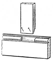
Fig. 347.—Fixing Muntin to Skirting. |
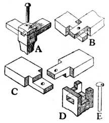
Fig. 348.—Joint for Home-made Cot. |
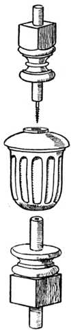
Sideboard Pillars, etc. (Fig. 349).—For economy, sideboard pillars are sometimes built up as indicated, the "shaft," the "base," and the "swell" being made up of three distinct pieces. Turned pins are left on the shaft and the base, and these are secured at the joint by the use of a double-pointed screw called a dowel screw. This does away with the necessity of reducing the squares at the top of the wood and thus getting the turning out of a large piece of wood.
Notched Joints.—Fig. 350 is a "notched joint," where two joists, or scantlings, cross each other, the object of the joint being to prevent the joists moving from their position without materially weakening them. For an end notch, see Fig. 352.
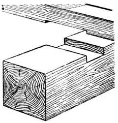
Fig. 350.—Notched Joint. |
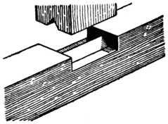
Fig. 351.—The Saddle Joint. |
The "saddle joint" (Fig. 351) is used for connecting upright posts to heads or sills of framing, and undoubtedly takes its name from its similarity to the way in which the saddle fits the horse. It does not weaken the framing as does a mortise and tenon joint, and shrinkage has little effect upon the joint. The "cogged joint," used for connecting purlins to rafter and joists to girders, is illustrated in Fig. 353.
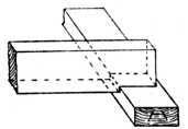
Fig. 352.—End Notch. |
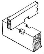
Fig. 353.—Cogged Joint. |
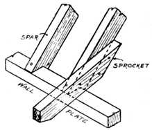
Fig. 354.—Birdsmouth Joint. |
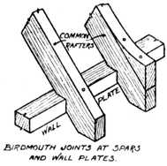
Fig. 355.—Another type of Birdsmouth Joint. |
Birdsmouth Joints.—Fig. 354 is a "birdsmouth joint," a simple joint which can be readily made by the handsaw, used when a spar fits on the wall plate. A nail is shown securing it in position.
Fig. 355 shows the birdsmouth joint where the spar runs over the outside of the wall plate, thus allowing a fixing for an ornamental finish.
Rafter Joint.—Fig. 356 shows an everyday joint, as used at the juncture of the principal rafter and the tie-beam in roof truss work. A sketch of piece A is shown separated, and it should be noted that the depth of the cut portion B should not be more than one-fourth of the total width of the tie-beam.
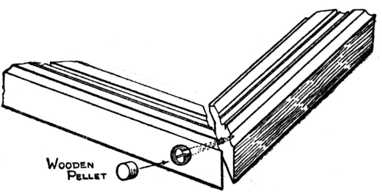
Pelleting.—Fig. 357 indicates the method of pelleting and screwing the corner of a picture frame. The mitre joint is first screwed and a pellet of the same timber is made to fill the hole which has been bored to receive the screw head. The pellet is glued in position and levelled off.
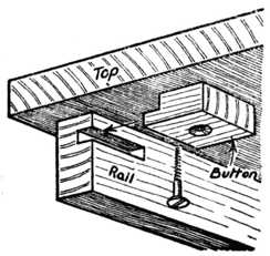
Patera Covers.—In cases where the style of ornament permits of it, patera covers are used instead of pelleting. Fig. 358 shows the jointing of shaped spandrails, etc., to carcase ends of light portable cabinet work, etc. A hole is bored about 3⁄8 in. deep into the end, and a screw is used to hold the shaping in position. After fixing the rail a small turned button, called a turned patera, is inserted in the hole, thus giving an ornamental finish, as shown in the front view. The turned patera is driven fairly tightly into the hole, but not glued. When it is required to take the article apart a chisel is carefully inserted under the edge of the patera to remove it, and the screw can then be taken out. This method is often used for the construction of light hanging bookcases and similar objects. For a bookcase having an end 8 ins. wide three of these turned buttons and three screws would be used to secure the shelf to the end. Pateras in different styles may be purchased from any dealer in woodworking sundries.
Buttoning.—The tops of tables, sideboards, etc., should not be fixed with screws in the ordinary way. At the front, screws can be driven upwards through the top rail, but at the sides and back, buttons should be employed, as in Fig. 359, so that the top is free to shrink. It is otherwise liable to split if immovably fixed. The tops of kitchen tables are usually fixed in this way, to allow for shrinkage.
Frames for Oil Paintings.—The method of making joints for frames on which the canvas is stretched for oil paintings is shown at Fig. 360. They are generally mitred at the corners and fitted with loose wedges. The four parts of the frame can be held temporarily by a piece of thin board while the canvas is being tacked to the edges of the frame. In the accompanying illustrations Fig. 360 shows the action of the wedges when tightening up the frame, the result being to open the mitre joint. Fig. 361 shows the position of the saw cuts for receiving the hardwood wedges. Note that the parallel groove is carried the full length of the material for greater convenience in cutting. The other groove is taken from the outer angle of the mitre joint inwards. The cut finishes with due regard to the necessary taper; see the dotted lines showing taper in Fig. 360. The grooves will be wide enough after being cut with an ordinary hand-rip saw, but for large work they are usually grooved on the circular saw bench.
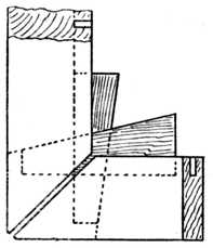
Fig. 360. |
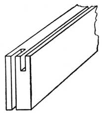
Fig. 361. |
Joint and Method of Wedging the Frames of Oil Paintings.
Corrugated Steel Fasteners.—It is now many years ago since the steel saw-edge fastener first appeared on the market, but probably 80 per cent. of amateur woodworkers have never yet sampled its advantages.
In appearance it resembles a miniature corrugated galvanised sheet such as is used for roofing purposes, with the exception, however, that the corrugations are divergent instead of being parallel and that one end is ground down to a cutting edge (see Fig. 363, A). They are made in various sizes from 1⁄4 in. to 1 in. in length, whilst in regard to width they are classed by the number of corrugations and not by their measurement.
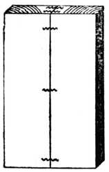
Fig. 362.—Jointing Boards. |
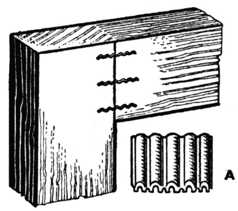
Fig. 363.—Jointing a Frame. |
The Use of Saw-edge Corrugated Steel Fasteners.
To use the fastener no special tools are required; it is simply driven in with a hammer exactly as though it were a nail; once in position, however, to get it out is worse than drawing teeth. The corrugations add to the strength of the device, the wood fibres closing around them, age and rust but emphasising their grip.
Wall Plugs.—At Fig. 364 four types of wall plugs are shown: a, the ordinary rectangular tapered wall plug to drive between the joints of the brickwork; b, the circular tapered wall plug as used to plug a wall after a star-shaped brick drill has been used; d, a twisted wall plug used for similar purposes to the wedge a, but considered to be superior in holding power owing to its twisted formation; c is another type of wall plug considered to have great tenacity by reason of its corrugations. Wall plugs are required in nearly all cases where it is necessary to joint woodwork to brickwork, as, for instance, heavily-framed silvered mirrors to the walls of shops.
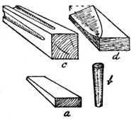
Fig. 364.—Wall Plugs, Four Varieties. |
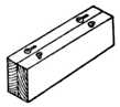
Fig. 365.— Slot Screwing. |
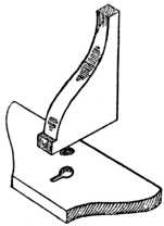
Fig. 366.—Slot Screwing a Bracket. |
Slot Screwing, or Keyhole Screwing, is a most useful way of joining light woodwork in such a manner that the fixing method is not exposed to the eye. A stout screw is inserted to within 3⁄8 in. of the head, as at Fig. 365. In the adjoining piece a hole is bored with a centre bit and a slot is cut with an 1⁄8 in. chisel. The two pieces of timber are placed together, and by sliding the upper piece forward the screw runs up into the slot or keyhole and secures the joint. Fig. 366 shows the application of the joint fixing a shaped bracket to the shaped shelf; the bracket and shelf are inverted in the illustration to clearly show the method of jointing. For heavy work special brass plates are obtainable for this purpose; one plate is let flush into the upper piece and the other plate into the lower piece.
Battening (Fig. 367).—A good method of joining cross battens to drawing boards and other wide surfaces is shown here. After boring for the screws, slots are cut so as to allow the screws to move along the slots when shrinkage takes place. In Fig. 368 a similar method is applied to secure the drawer bottom to the drawer back. If shrinkage takes place in the drawer bottom and it leaves the groove in the drawer front, the screws are slackened, the drawer bottom is knocked up into the groove, and the screws again inserted. For drawing boards, etc., specially made elliptical-shaped slotted brass socket cups are made to receive the screw heads.
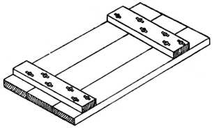
Fig. 367.—Battening. |
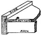
Fig. 368.—Drawer Bottom Joint. |